Jonathan Thomas

FSAE Fuse Rig In progress
NYU Motorsports, Fusion 360, PlatformIO, Teensy, C/C++. June 2026 to present.

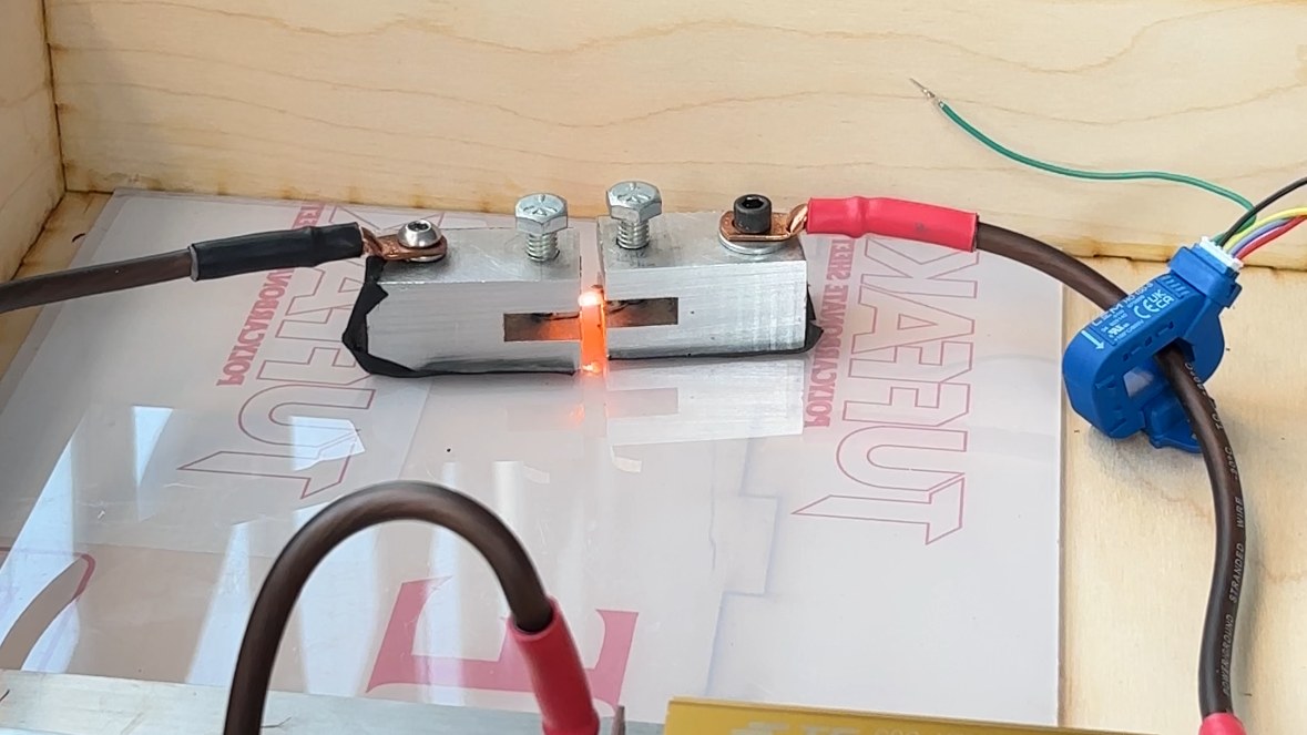
A copper cell fuse glowing orange-hot between two aluminum clamps inside the rig, with a blue Hall effect current sensor clamped around the cable on the right
A fuse glowing mid-test, with the Hall effect current sensor clamped around the cable on the right.

Every cell in our accumulator has its own small copper fuse, and those fuses have to be rated before the car can pass FSAE tech inspection. I built this rig for NYU Motorsports to test them.

We used it to rate our cell fuses at 35A, which resolved a tech inspection failure. It also replaces last year's setup with a safe, enclosed, isolated environment that meets electrical isolation protocols.

Fusion 360 vs. the real thing
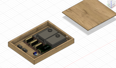
Fusion 360 model of the fuse rig: an open wooden enclosure holding power resistors, boards and connectors, with its lid lifted off
The model in Fusion 360.
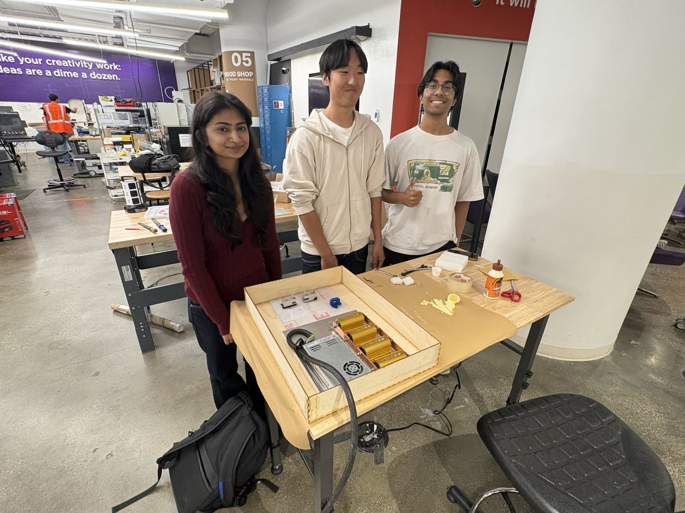
Jonathan and two others standing behind the finished fuse rig: a wooden box holding the power supply, gold power resistors and the fuse clamps
The finished rig.

How it works

The rig is monitored by a Hall effect current sensor and a thermistor, both wired to a Teensy. The firmware captures current and temperature data through each fuse test, so every rating comes with a record of what actually happened.

Before testing, I checked the parts on the bench. The gold power resistors are 0.1 Ω, and a 4-wire measurement read one at 0.0992 Ω.
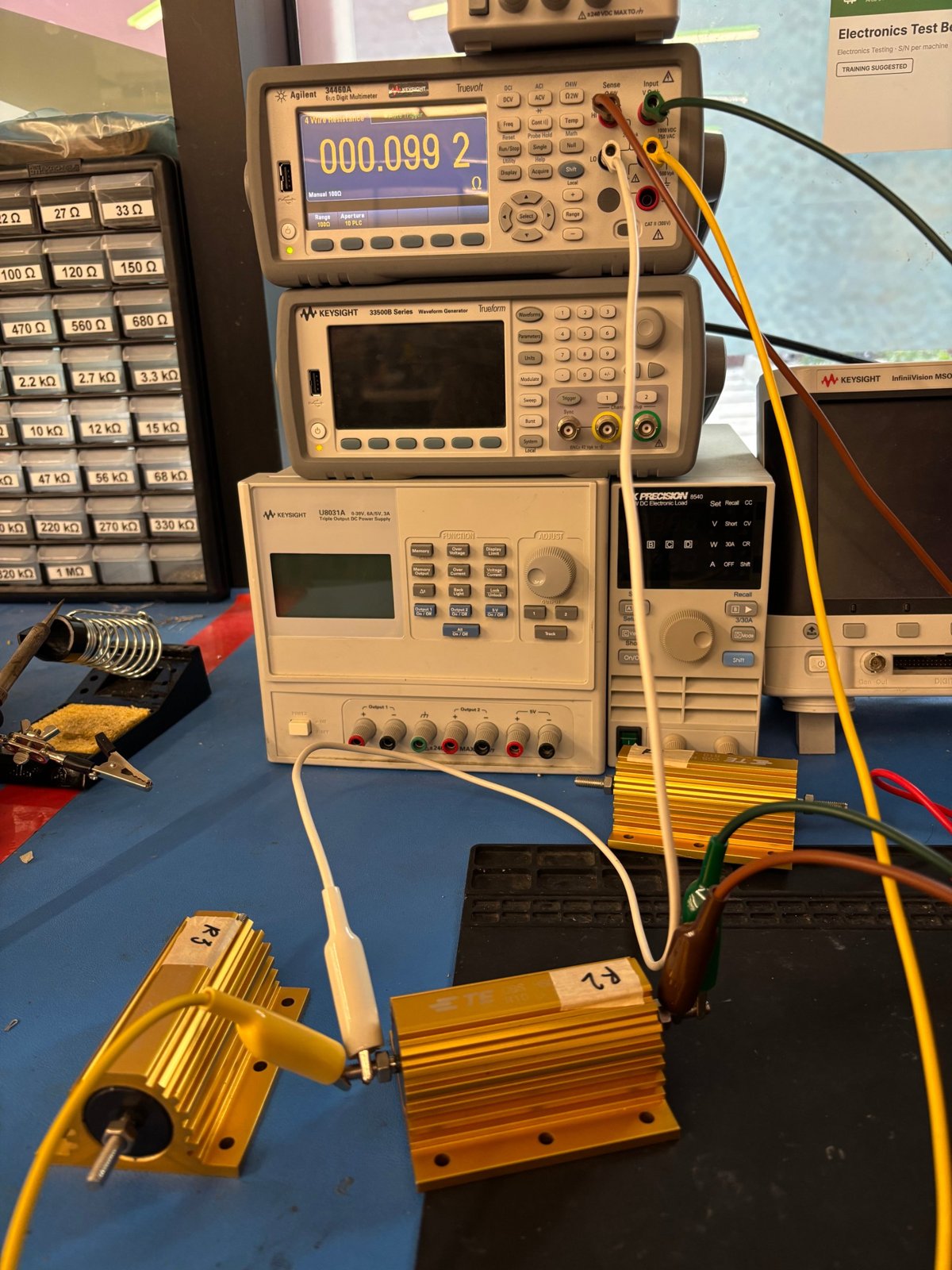
Two gold power resistors labeled R2 and R3 on a bench, wired to a Keysight multimeter showing a 4-wire resistance of 0.0992 ohms
Measuring a power resistor with a 4-wire measurement.

Making and breaking fuses

Milling fuses out of copper sheet.
Popping one in the rig. Watch for the spark between the clamps.
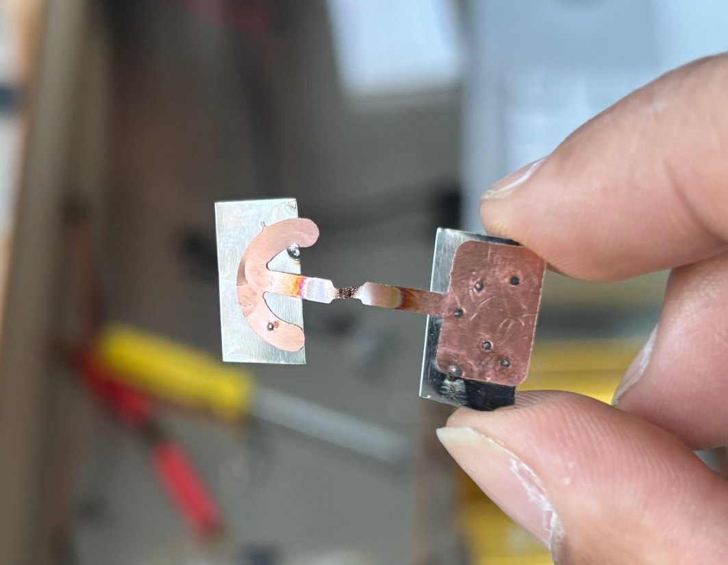
A copper cell fuse held between two fingers, broken at its heat-discolored narrow neck after a test
What's left. It broke at the narrow neck, right where it's designed to.